This time, I decided to try a rather novel approach to a low-cost DIY CPU block, where the most expensive tool being used was a drill press. (can be done even without it)
Most amateur blocks are the sandwitch type, 2 thick pieces of metal, one thick and one thin or a thick piece of metal and thick piece of plastic.
My construction is of the last type, using 10mm (10.2mm) aluminium, but the top where the hoses are connected to is made from 10mm LDPE. For some weird reason, a lot of people go for acrylic, which from my personal failures in attempts of this construction I can say is the worst possible choice one can make.
Here's why - 1) its brittle (tapping this is not for the fainthearted) 2) it's not particularly strong, this coupled with the brittleness means it's very easy chip/crack during drilling 3) it's fairly expensive 4) hard to come by in small, but thick pieces.
So why did I choose LDPE? 1) you can buy 10mm boards dirt cheap, search for "cutting boards". They can be had even thicker, but the price starts to take off quite rapidly after the 10mm mark. 2) availability. These cutting boards can be bought even in convenience stores, online stores have them in truckloads and keep trying to undercut each other on the price, bringing us back to n.1 3) while being quite tough, it's also soft. My construction doesn't use a seal, the screws squash it against the metal so well it doesn't leak. Also, machining it much easier, all you have to do is keep the tools sharp.
Metal time!
 |
| 68x76mm aluminium block (yup, it's AM2, 2+ and 3 compatible) |
 |
| some more aluminium |
As you can see, the block is mabe by drilling a bazilion holes (OK, more like 42 + 16 small ones for the fasteners) , first with an approx. 5mm drill, then the final 8mm. The remaining "islands" were twisted/torn off with pliers. So ghetto. Final cleanup is done by a "large" oblong mill for a Dremel-like tool.
If you don't have one, get one, you'll love it.
 |
| Awesomeness right here |
This is how the block sat for 2 years. Then I had a brainwave with the LDPE cutting boards and bought one as building material and one as an actual cutting board. And two G 3/8 set taps. And a 14,9mm drill bit, which turned out to be useless. (most drill chucks, including the one on my drill are smaller)
Along with the the LDPE idea, I also thought about the hoses. Turns out that you can buy a 50cm piece of 14x8mm steel braided rubber hose, with crimped-on G 3/8 male and female fittings on each side, all for the equiv. of $3.2 (exchange to $ on 25.6. 2014). 30 and 40 cm pieces cost a few cents less.
| mmmm, braiding.... |
Yes, they are meant for water appliances, not PC cooling, but for the cost of 1 stainless steel fitting* that was made for PC cooling, you can get:
- a nice hose with all the fittings (crimped!), which are nickel-plated brass (more on that later*)
- a brass G 3/8 to 1/4 adapter (PC radiators seem to come only in G 1/4)
- a piece of teflon tape to make sure it doesn't leak.
Technically you can go nuts and have the hoses made with G 1/4, but the quote I was given (by a small company specialising in hydraulics, they have the crimp tool) was 3x as much, so I opted for pre-made with adapters.
Now, as for the * - if you google galvanic corrosion, you will quickly find that using stainless for water cooling is a dumb idea.
1st up, pretty much all types of stainless steels are quite far away (corrosion WILL** occur) from copper, 2nd stainless is the cathodic one, meaning copper (of which the expensive radiator thatIcan't(yet)fabricatemyselfsoIhavetobuyit is made of) is the one that is going to be eaten.
**For galvanic corrosion to occur, you need: 1) dissimilar metals (got that) 2) electrolyte (watercooling) 3) conductive contact. So, using stainless on your shiny new copper rad that costs as much as 4gb of RAM is a no-no.
As for bare or nickel-plated brass - they are practically next to each other in the relative electronegativity, so corrosion will be minimal.
But what about the aluminium block, whose electronegativity is on the other side of the chart (copper, brass and nickel are somewhat in the middle)? Well, for one aluminium is the anodic one (so IT gets eaten, not the expensive stuff), second - no contact. The LDPE block which holds the hoses is keeping them well away from ever touching the block, and if I ever get to actually mounting the system, the rad will not be directly touching the case.
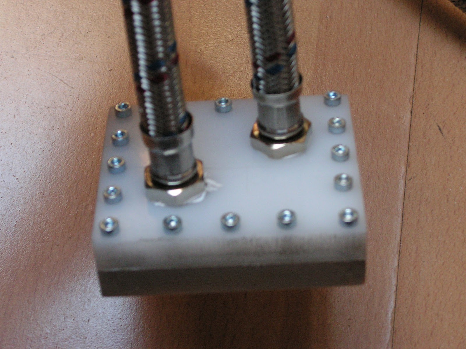
So, enough bullshit, how does it look?
 |
| Not too bad given the cost is less then the cheapest of Chinese of waterblocks on ebay |
 |
| Plenty of more room for even bigger ones :D |
 |
| Crap picture n1 (camera seems to like the floor instead of my waterblock) |
 |
| Crap picture n2 |
 |
| Shiny! |


