 |
| Like this one |
In my case, the load is a LVDS panel signal converter (and a TFT LCD panel with it's backlight module). Once everything was stable and running, the PSU could crank enough juice and keep the voltage high enough that the converter logic didn't complain. But when starting, the current draw peaked at 2A and the logic kept shutting down, because the voltage dropped below 11,5V. (Not sure why that mattered, since all of it's internal power supplies need less then that)
So, surgery time...


Red lettering notes what was added (it should be pretty obvious that a few parts have been removed prior to that).
A) is the new voltage divider, consisting of a 3k9 and 1k resistor.
B) is an additional low ESR capacitor, 1mF/25V (unncessarily too much, but it's what I had on in the junk pile)
C) is a 10µF tantalum cap, needed to keep the TL431 out of it's unstable region
D) TL431, scrapped from the same dead PSU as the cap in B)
E) a new 150Ω resistor (instead of 100Ω from previously) for the optotron (no idea what it, just assumed a 4N35 knock off, which it apparently isn't*)
*With a 3k9 and 1k resitor divider and a TL431 voltage reference (2,5V) the formula Vout=(R1/R2+1)*Vref
 |
| A-PSU;B-current(x10 in mA);C-voltage;D-30A/300mV shunt;E-bigass rheostats as load (yes, a rheostat, you read that right) |
Nope.
Seems that the mystery optocoupler is somewhat different from a 4N35 which I assumed it would be. But we are still within margin.
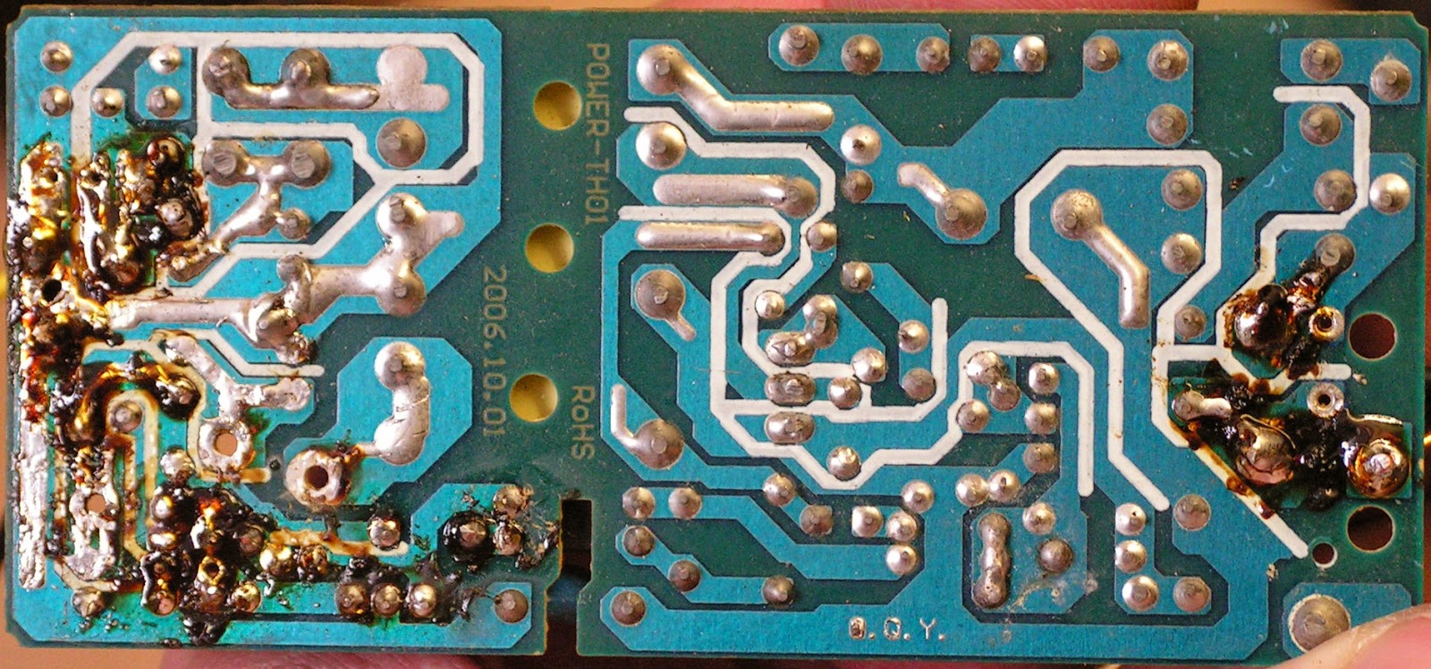
The powersupply is surprisingly well built (considering that the entire set of the converter cost the equivalent of $20, with import fees, taxes and all that crap), the main transitor is a STP4NC60FP (not sure if real or knockoff) and the primary and secondary sides are well separated. Eve the filtration caps don't seem like the cheapest crap that's out there.
The primary side of the power supply looks very similar to this one. The secondary side (now) looks somewhat like this. The resitor divider is obviously different and there is a 10µF bipolar cap connected to the cathode and anode of the T431. If you leave this out, the TL431 will enter an unstable region (fig. 15 on page 7) and start to oscillate, since the LED in the optocoupler has capacitance.
In my case, that causes an audible whine of the power supply from no to full load, and quite notable voltage ripple (no footage, sry). With the cap it oscillates only when the load drops below approx. 120mA (even then the ripple is smaller and barely audible), which will not be a problem, since when on, the TV draws about 1A, and when on stand-by it will not mind the increased ripple.
Edit: I fucked up and read the theory wrong, the cap is supposed to be between the reference and ground (close to the anode). Once there, the PSU exhibits similar ripple behavior with the exception of audible noise - there is none whatsoever, regardless of the load.
Running with a 1A load
Relaxation oscillation with approx. 90mA load
Sorry for the crappiness of the footage (and lack of grid or frequency, the scope is from the 60s...EMP resistance comes at a cost :D), but hopefully it's clear what goes on in the power supply.