Sunday, May 28, 2017

How to load Taulabs onto an Openpilot Revolution mini

While Sparky2 is probably the best go-to board for Taulabs, the Revo mini can actually be bought, since it's usually in stock...
So instead of waiting who knows how long for someone to have a Sparky2 in stock, I bought a Revo mini. If you compare the 2, you'll see that there's only minor (but still important) differences.
Revo mini schematic vs Sparky2 schematic
There's just the issue of Taulabs not detecting the board with the Openpilot bootloader. You can try and go the masochistic route, or you can actually do it the easy way.

  1. download and install both Taulabs and Librepilot groundstations.
  2. download the Linux version of Taulabs (regardless of your OS) and extract, (7zip works well) somewhere in there you'll find the bootloader *.bin file
  3. use Librepilot to:
    1. HALT the MCU and go into bootloader mode (firmware tab)
    2. !!!back up the original firmware!!!!
    3. select the proper *.bin file (only the bootloader!), tick the warning boxes and upload the bootloader. If you fuck up somehow, it should still be possible to rescue the board with the previously saved firmware.
  4. close Librepilot, open Taulabs, go to firmware tab, it should now recognize the board in bootloader mode
  5. load latest firmware release, boot the board, check if it works.
Done.

Sunday, April 2, 2017

Console over RS232 on a Nortel 4550t switch


  1. straight, female-female cable (seriously check that it's straight, pins 2 and 3 must not be crossed)
  2. serial port (TTL-level devices don't seem to work - at least it didn't for me - so make sure it's a real RS232)
  3. some terminal program, putty works well enough
  4. select the right COM port, 9800 baud, 8N1...the bog-standard for slow serial


If you see text while the switch is booting, you're golden. If not, something is not working the way it's supposed to.
Before you can start wreaking havoc in the console, you have to wait for the switch to boot. There is a procedure to get console before boot, but that is generally useful only if you locked yourself out.
Once you get the ASCII-art logo, press CTRL+y, then type "en" or "enable". Let the typing begin.

Sunday, November 13, 2016

Using a Dell D220P-01

In case you don't know what a Dell D220P-01 is - it's a power supply for the SFF version of Dell's Optiplex 740 series PC. The neat thing about it is that unlike a traditional ATX PSU, this one is 12V only, so you get 220W @ 12V (18A) maximum and the PSU should not complain too much.
Another neat thing about them is that the PCs are legitimately junk, so you can get them even for free.
Stolen from PcHub.com
The pinout is in the picture, "P5" has to be connected to ground in order for it to turn on. Unlike newer server PSUs, this one can be connected straight from the start.
If you're like me and don't feel like butchering the connector, you'll need a breakout board. The connector is mechanically (!not electrically!) compatible with an 8-pin EPS12V power connector (plug is Molex 39-01-2080, PCB socket is  Molex 39-28-1083, terminals are Molex 39-00-0168 and Molex 44476-1111).
The 8-pin PCIe power connector is different with the placement of the square and hexagonal holes and is not mechanically compatible...not like that will stop the 200 pound gorilla from trying to jam it in...
Needles to say that if you plug this (and turn it on) into an EPS12V connector of a working motherboard, you will turn it into a non-working one, as the voltage is inconveniently reversed and the power supply will turn on. Results may vary from nothing at all to a spectacular fire and mini explosions of the caps.
"EPS12V"
stolen from http://www.playtool.com/pages/psuconnectors/connectors.html#eps8
If your junkbox doesn't contain a motherboard with an 8-pin EPS connector, fret not, there is an alternative!
24-pin ATX...cut on the red lines...
stolen from wikipedia

Yep, it's not a true hack unless it involves a hacksaw!
side note - on any newer-ish junk motherboard, I suggest cutting the connector out, as the inner power layers use thicker copper (for heatsinking) and carry away heat from the soldering, making it very difficult.

As said earlier, plugging this PSU here to the MB is also not a good idea, although it should not turn on (results may vary). If the PSU does turn on, it will be short-circuited, if it "wins" over the short (burns through), it will send 12V to a 5V line...

Here's my quick and (really) gritty breakout board.
front

back
Yes, it's fugly, yes, it could've been nicer...I was going for "fugly, but functional". The crapton of solder should make sure that it can actually carry the 18A the PSU can deliver.
I kept the +12V rail from being at the edge, as it lowers the chance of an accidental short. The brass washers are actually soldered to the board.


Saturday, November 5, 2016

Smaller & lighter

While Totally not a bomb Mk II was useful for testing, it was a little too bulky even for the 1:10 car, so it was time to go shopping again...

BOM:

  • 1x Raspberry Pi Zero 1.3
  • 1x 0.5mm pitch to 1mm pitch 15pin FPC cable
  • 1x TL-WN722N
  • 1x male RSMA connector with pigtail
  • some Kapton tape
  • enough 0.5mm sheet aluminium to make a box
  • ?x M2 screws
  • 1x XL6009 adjustable step up down Converter (DSN6000AUD)
The procedure:

1) Liberate the TL-WN722N out of it's plastic casing
2) perform UglyHack™ No.1 by desoldering the USB connector and solder on wires instead. Solder the other end fo the data lines into the USB port of the Rpi and solder the power to the power USB port of the Pi. PP1 is +5V, PP6 is gnd, PP22 is D+ and PP23 is D-. Twist the data lines to avoid weird shit from happening.
Grade-A hacking here!
the Kapton tape really is necessary...
Make liberal use of Kapton tape, covering all the exposed pads to avoid short circuits later.
3) Perform UglyHack™ No.2 by desoldering the RSMA connector and soldering on the pigtail one.
Again, Kapton tape is a must, not only as an electrical insulator, but also strain relief.

4) add the DC-DC power module (forgot pics, sry)
5) make an aluminium enclosure like so:
The other half is just a rectangular "U" shape, some of the holes are actually threaded.
6) Jam everything in, making sure that nothing is touching where it shouldn't.
In my implementation, the Pi is held a few mm away from the wall with screws and nuts on flexible washers. Some day I'll probably add a thermal pad between the main IC and the box, it does get warm.
The metal shield of the WiFi dongle is in direct contact with the wall to aid cooling, as it gets fairly hot when running with EZ-wifibroadcast. The DC-DC module is not even warm to the touch, so it can just float in the middle.
7) connect camera, strain-relive the cable so it doesn't get damaged.
Bottom scale is mm, top is inches.
Definitely could be made even smaller!

8) attach to desired mode of transport
Totally not a bomb Mk III
Camera holder needs to be adjustable...
Antennas for WiFi and RC
A few notes:
  • The antenna arrangement here is not ideal, the WiFi and RC systems interfere with each other, they should probably at least be further apart... (or I should use 5 GHz WiFi).
  • EZ-wifibroadcast on default runs outside of allowed WiFi bands (shhh, don't tell anybody...) and I keep it that way, there really isn't anything critical or even important using this band and it keeps the mutual interference with other WiFi to a minimum.
  • There are 5 GHz modules that are known to work with wifibroadcast if you want to avoid interference in the 2.4 GHz band.
  • The XL6009 module should safely operate between 4V to 30V. Pushing the voltage to the limits is asking for it.
  • The XL6009 is superior to LM2577 in that it runs at 400kHz instead of 50kHz, meaning the inductors can be much smaller.
  • If you feel lucky or actually know how to design a better DC-DC module, you can run both the dongle and Rpi directly on 3.3V. Be however aware, that if you fuck up, you'll fry them both.
  • If I ever make this smaller, I'll use one of the fancier DC-DC controllers that run at 1MHz, so the inductors are even smaller and the ripple is easier to filter out.
  • I advise using EZ-wifibroadcast as it boots much faster.
  • Last but not least, keep in mind that the sytem draws slightly over 2.5W and most of this is dumped as heat between the Rpi and the WiFi dongle, you have to allow air to flow around the box, otherwise it might overheat.

Saturday, April 16, 2016

Wifibroadcast - measuring latency on a laptop

My method of measuring the absolute latency scene-to-screen involves the camera looking at the receiver screen which is partially obstructed by a smartphone running a stopwatch, all being recorded by a Casio EX-F1 at 600fps.


The darker one is the smartphone screen, the lighter, grainy one is the laptop. I picked shots where both numbers are not blurred as they are changing.
Phone has an LCD, not AMMOLED display, so it tends to blur fast changing stuff. Both displays (phone and laptop) should be TFT, so about as fast as a consumer-grade LCD can be.

The mathematical average of these 10 shots is 197ms. Not too bad...

Sunday, April 10, 2016

Wifibroadcast receiving on a PC

Yup, you definitely can watch on a PC. (And there's no limit on how many! :D)
Tested on a Lenovo x230 running Ubuntu 14.01 LTS x64 with a TP-Link TP-WN722N.

Installing wifibroadcast:
open Terminal or some other commanline and input:

  • sudo apt-get install mercurial libpcap-dev iw
  • hg clone https://bitbucket.org/befi/wifibroadcast
  • cd wifibroadcast
  • make
If there's no screaming or error, you may proceed with connecting the wifi card and waiting until it lights up. Then proceed with setting it up:
  • cd $HOME/wifibroadcast
  • sudo ifconfig wlan1 down
  • sudo iw dev wlan1 set monitor otherbss fcsfail
  • sudo ifconfig wlan1 up
  • sudo iwconfig wlan1 channel 13
Run the program with:
  • sudo ./rx -b 8 -r 4 -f 1024 wlan1 | gst-launch-1.0 -v fdsrc ! h264parse ! avdec_h264 !  xvimagesink sync=false
Once there is a valid signal from the transmitter, the wifi LED will start flashing and shortly after you should see a window with the stream pop up. 
To infinity and beyond!

You can close it with ALT+F4 and stop the wifi with 

  • sudo ifconfig wlan1 down

To start it up again, repeat the setup (no need to install anything again) and run the program. Here I'm using wlan1, because I'm assuming that like me, you'll be using a laptop, so wlan0 will likely be taken by the internal wifi card. This may however not be the case, unless you are sure, check with ifconfig

Scripting it because typing everything is for noobs

1) create a new file (with no extension) and open with a text editor of your choice (I used gedit)
2) paste the following into it:
  • cd $HOME/wifibroadcast
  • ifconfig wlan1 down
  • iw dev wlan1 set monitor otherbss fcsfail
  • ifconfig wlan1 up
  • iwconfig wlan1 channel 13
  • ./rx -b 8 -r 4 -f 1024 wlan1 | gst-launch-1.0 -v fdsrc ! h264parse ! avdec_h264 !  xvimagesink sync=false
3) save to a convenient place, like /home
4) type the following into terminal, replacing "script_name" with the actual one you saved:
  • chmod 755 "script_name"
This gives the script read and write permissions.
5) to run the script, you only have to type:
  • sudo ./script_name
Again, replacing "script_name" with the actual one. You have to use sudo, because it needs permissions to tweak the wifi dongle. Without it, it'll never run.

Saturday, April 9, 2016

Dual boot for Windows 8 with Bitlocker and Ubuntu 14.01 LTS, UEFI version

  • Make sure you are booting in UEFI, not legacy mode. Seriously, check that shit.
  • Turn off secure boot.
  • Windows 8 goes first. For good measure, make sure the drive is GPT, not MBR. This can be done even in the install by clicking the "repair" and clicking your way to a commandline (tons of how-to's on teh interwebs)
  • If you need to make a UEFI-capable install USB flash, simply use diskpart to: 1) clean the drive 2) convert to GPT 3) create a primary partition DO NOT mark it active!!! 4) format it to FAT32 5) assign a letter. Close Diskpart, if you have a ISO somehow extract it (W8 and later can mount ISOs as a virtual drive; winzip can open it like an archive), dump the contents straight to the flash.
  • Create a patition for windows, make sure you leave enough space for Ubuntu, 10GB seems to be the recomended minimum. Windows installer should tell you that it's going to create additional pratitions, there should be a total of 4 including the one you made.
  • After the install and initial config, set up Bitlocker, save the keyfile outside the encryped drive, encrypt drive. Take ownership of the TPM. Reboot and make sure it works.
  • Disable fast boot, otherwise stuff WILL BREAK. There's little difference having it on for SSDs, magnetic drives are a different story though. The checkbox can be found in power management ->buttons setup ->the top "change what you can't now..." checkbox -> allow fast boot (uncheck).
  • Install Ubuntu. Bootable USB the same way as for windows. I chose 14.01 LTS, but I see no reason the newer versions would not work. Run the setup in "install alongside windows" mode. Partitions can be shrunk later. Make sure you note down all the passwords and pass phrases you set up. Test Ubuntu boot.
  • Test Windows boot. Most likely it will require you to input the key that you should have saved outside the encrypted drive. If you didn't, you're a dumbass and now have locked yourself out. Best start over.
  • boot Ubuntu, Change UEFI boot order via efibootmgr - in terminal type sudo efibootmgr -v  to see whats going on (you'll see quite a few  things with 4-digit numbers, and the boot order), then type sudo efibootmgr -o with the altered boot order. You'll most likely be switching the 2nd for the first. This is not fuck-up-resistant! You screw up - no worky worky!
  • If windows boot works, reboot again. If it keeps requesting you input the key every time you boot, you have to take ownership of the TPM again. If the greedy bastard keeps insisting you input the key over and over again despite you taking ownership of the TPM, something's fucked up and you have a long Google session ahead of you.
  • You will most likely not see any mention of Ubuntu during boot anymore, but fret not, try mashing whatever key brings up the boot menu before it starts booting, you should see "windows...something" and "ubuntu". This will be the way for choosing. Should also work for additional UEFI installs, the names seem to match the directories in the \EFI  
  • Turn secure boot back on
  • Install drivers and crucial software for both systems, make a disk image. Seriously, do that, the time you save when reinstalling is makes this worth it. Save the keys, passwords and passphrases with the image, as it's useless without them.
  • Enjoy your dual-boot.

This was done on a Lenovo x230 running an aftermarket SSD, Windows 8.1 and Ubuntu 14.01 LTS, all from UEFI-capable bootable USB flash drives. Both OSs run in secure mode with no bitching.
The boot menu is slow to load (10s for me), but that seems to be feature, not a bug.
Your results may vary, as i uderstand UEFI implementation is not perfectly the same for all PCs.

Thursday, April 7, 2016

Dual boot for Windows 8.1 and Ubuntu with encryption galore, MBR version

word of warning - this is for patient people only. If you are known to chimp out after 4 hours of something refusing to work as it's supposed to - I'd suggest something different...

On to the magic, why would you do this?
I have a Lenovo x230 laptop to which I cheaply bought windows 8.1. Once you get Classic Shell installed, it even mostly feels like W7 which boots insanely fast. I'll gladly admit that I'm a windows guy, it's what I feel at least slightly comfortable working with since I practically grew up with it. Venturing into Linux territory usually means Google is working overtime and it takes a fuckton of time to get anything done, because everything is different. Don't even get me started on OS X.
That being said, Linux allows for certain unicorns that are not possible (or horribly difficult) on Windows because of the way the drivers work. Monitor mode for WiFi adapters is one of those things, extremely useful if you wish to do any type of poking with WiFi, good or bad. It's what allows Wifibroadcast to shove packets into the WiFi adapter without caring where or if even at all the end up at. It also allows receiving mangled packets (only some chipsets though, Atheros has long history of that).

Why would you do it like I did?
These days, a healthy dose of computer paranoia tends to be quite reasonable, given how much sensitive info can be extracted out of your daily use PC. Just the windows password is the equivalent of a 1 meter high decorative fence around your house. Enough to make normies understand that you don't want them rummaging through your stuff, but obviously very easy to defeat by multiple methods. So, if you want something a little more resilient, there's encryption.
Now common 256bit AES is enough to make even American 3-letter agencies pissed (btw it's approved for use on top-secret information), your average tech-sawwy criminal has no hope in hell of defeating the encryption itself, (it's much easier to literally beat the password out of the owner) at least not in his lifetime.
Naturally, the one thing I was satisfied with on previous OS versions doesn't really work for W8, so I have to use Bitlocker. Because of how this thing works, IT needs to be the first thing to boot, otherwise it's a no-go. Yes, having to boot most of windows only to tell it that you want linux and letting it reboot is kinda silly now that I think about it, but until M$ acknowledges that they could do a better job on the bootloader, it's the only way of running it like this.
If it weren't for the Bitlocker part, you can happily use the automated install and let linux configure everything for you. But if you need your tinfoil hat, it's hacking time!

Loosely following this guide, (loosely meaning not everything was exactly acording to this guide, there were others as well...), I created 2 partitions for Linux, one for root, the other for swap. The root one needs some space to be usable, exact figure depends on what you want install, but mine is roughly 20GB. Swap should be more then happy with 4GB, although I used 8GB. Don't know why (the machine has 8GB RAM), but I saw this once the win was set up and I didn't feel like doing it again (can't move the boot partition without breaking booting).
Then I let windows create it's boot partition and gave it some reasonable space for C:, roughly 50GB and let it install. Once that's done and you have most of the stuff installed, turn Bitlocker on, configure the TMP, then turn it off again. (where have I heard that before...oh right, I have the misfortune to do IT support for a living...).
Once that's done, I'd suggest making an image of the machine, because if you fuck up the following steps, it's really hard to fix. Much easier to just restore. I personally like Clonezilla. I tend carry in on a multiboot flash along with other goodies.
Install your Linux of choice, but you can't use the "auto" install, you have to do it manually. Tell it to use the bigger linux partition as /root and format it to EXT4 and to use the swap as...swap. Install everyhing. Once that's done, DO NOT let it place the bootloader into the MBR (if you do, windows will not boot), instead plop it into the /root partition.
If you've customised the crap out of the thing during install and windows STILL boots, make another image, saves time if you fuck up the bootloader.

Now comes the "fun" part. (link to source)
Boot some kind of linux from a flashdrive, somehow determine what is your partition of interest (gparted has a nice GUI; or just fdisk -l) and make note of it, it has to be the /root (or whatever you stashed the bootlader into). Do dd if=/dev/sda1 of=/tmp/linux.bin bs=512 count=1 , replacing sda1 with the patition with the bootloader.
This will make and copy linux.bin into the tmp folder (it's in /root). From there, copy it either to a flash drive or if you feel like it, plonk it straight into the root of C:. Boot into windows.
Launch cmd with admin rights and do bcdedit , it should dump the current state.
Now, do bcdedit /create /d “GRUB” /application BOOTSECTOR , you can replace the "GRUB" with whatever you want to name the entry (it will show up as the selection of what to boot). You will get a long GUID in curly brackets, copy that shit.
Now, do bcdedit /set {GUID} device boot , {GUID} is what you should have copied from the previous step.
Next do bcdedit /set {GUID} PATH \linux.bin
then bcdedit /displayorder {GUID} /addlast to put it below the win8 selection,
then bcdedit /timeout 10 , the number is timeout in seconds. I recommend less, 5s is plenty enough.
The final step is bcdedit /set {LinuxID} device partition=C: , this tells it which actual partition it can find the linux.bin.
Once you feel you did all that you should, do bcdedit again and check that the second entry looks something like this:
Real-mode Boot Sector
---------------------
identifier              {a33bafb4-fc1d-11e5-8259-3c970e62ae2e}
device                  partition=C:
path                    \linux.bin
description             Ubuntu
Obviously, the identifier will be diefferent and the description will be whatever you made it.
The device part is what took me almost 8 hours of trying various things, including different distros and what have you, only to realize that there is no way the system can know where to look for the bootloader. After extensively searching how to use the bcdedit /set , I found this, did it, tested it, found it working exactly as it should, did the "yatta!" and went on to post a comment to the M$ blog article, only to find THAT EXACT THING THAT TOOK SO LONG TO FIND was there all the time... read the comments...
If both systems boot, turn on bitlocker, make sure TPM is running (otherwise you'll have to manually input the long key every time) and let it encrypt.

Last but not least, make a partition on the remaing unused diskspace and format it to NTFS. Then install Truecrypt (or other encryption SW of your choice) on both systems and encrypt the partition, it will serve as a safe datastore that both systems can access.

Now make the final image of the machine and store it safe, unless you want to ever go through this again. Enjoy your reasonably secure dual boot system.

Saturday, April 2, 2016

polishing the turd some more

To address the light performance and increase the view angle, you need a different lens.
To hold the lens, you need a lens holder. Like this one. (not optimal*, but can be made to work)
Before you buy said lens holder, note that the hole spacing on the camera module is 21mm, not 20. Holders with 21mm spacing seem magically more expensive, even though they are made from the same material using the same technology. Before you put on the new lens, the old one obviously has to go. This needs needle-nose pliers and a bit of persuasion, but it's not terrible hard.
Because of the hole spacing, I had to secure the holder with wire and then glue it to the PCB. Then I could screw in the lens and focus it.

So, without further ado, I present:

Totally not a bomb mk. II

Not a bomb even in the slightest

On the back is a different switchmode converter, not sure about the topology, but it goes both up and down. Uses 2 inductors and doesn't invert the output voltage. buy here
Efficiency is not all that awesome, still draws 2,68W, so pretty much n=80%. Also, it makes audible noise, (discontinuous mode), so it's not matched well for the current draw...

voltage is inverted, so it's rising in the graph
New toy btw. Would be perfect if they added some math functions to the app.

trash TV in action
Viewing it on the trash TV, the latency is barely perceptible, probably close to what the project author measured.


Latency seems to be betweeen 140-170ms, so unless you need to go crazy fast, quite usable.

Friday, January 1, 2016

Polishing the turd

After some looking at the datasheets and doing some number crunching, I came to the conclusion that the inductance of the buck regulator is too small, not too large...
Measuring the size and winding of the original one, inductance calculators gave an estimate of about 300μH, which is reasonably close to 330μH that it probably was.According to the datasheet, for 12V input, 5V output at 0.45A, I should be using a 470μH inductor. So I dug through my junk pile, found a T106 size iron powder core that was green with one side blue, meaning it has a permiability of 75 and is good to about 1MHz.
"Ring core calculator" (freeware program) said I need 70 turns (243cm of wire), couldn't find what wire I should use, so I just grabbed the first reel I came across, 0.255mm diameter which should be sufficient. Half an hour of winding later, I had in inductor that replaced the original one, only downside is that it weighs 36g instead of the 27g of the original one...the core is ridiculously large for such low current, but I don't have anything smaller that can fit enough turns for 470μH.

It's quite interesting that with switchmode regulators, drawing less current means you need more inductance to function properly, and vice versa for larger currents, where the core size is predominately dictated by wire thickness, as you need just a couple of turns. (but you have to be able to physically stuff it in/on the core)


For 5V out... © ON Semiconductor
The number is inductance in μH, the letter has to do with current rating.

TL:DR - input power is now 2,81W (instead of 3W), making n=76,6%, so - yeah, improvement, but nothing to receive a prize for...

Thursday, December 31, 2015

FPV for the 21st century

Saw a couple (of dozens...) of youtube videos with people mounting FPV to various RC things. The videos from cameras themselves looked fantastic, but to transmit the video feed to the pilot, an analog link is traditionally used. While the transmitters and receivers are small, relatively cheap and yet use fancy modern stuff like digitally controlled PLL tuning, it's still analog video, even at perfect conditions you have 576 visible lines at most, a far cry from 720p or 1080p we are used to in digital video that has been around for almost a decade now.
There are a few working attempts at transmitting amateur video over DVB-T, but the problem is that the cheapest variant (to this day) requires a modulator that costs $170-$230, not very cheap. Does not include the cost of any other vital part (camera, RasPi...)
Others that I saw use software radio, this particular one a BladeRF ($420), and I would guess that it should be possible to use HackRF (~$300, depending where you buy it from) or the HackRF Blue ($215, or $150 for a "factory second" version), which is a cost-optimised version of the HackRF. One more that I remeber used an URSP 1 (>$700, the newer versions cost even more).
All of the software radio versions however require a fair bit of floating-point maths to be done, way more then a measly Raspberry Pi could do, so they are not practical as FPV transmitters.

So, not being happy with the analog quality and the pricy-ness of the digital solutions, I've been putting FPV off for over 2 years now.
Recently I noticed Wifibroadcast, which simply put uses "monitor mode" to force certain wifi chipsets (only some can do this!) to completely change the way the protocol works, which allows not only to receive mangled packets (under normal operation wifi discards packets whose CRC does not match), but to also transmit modified packets. One other important feature of Wifibroadcast is that it's one way, meaning that the transmitter does not need to receive any conformation from the receiver (again, under normal wifi operation, the transmitter keeps re-transmitting a packet until it gets an ACK from the receiver or times out and quits trying). The combination of one-way transmitting and ability to receive mangled packets means that with degrading conditions (like the transmitter getting too far) the link fails "gracefully", not instantly like normal wifi would.

So, (my) shopping list:

1x Raspberry Pi Model A+ with Coupé Royale Pibow (£20.83 GBP (~$29.5) from pimoroni.com )
1x Raspberry Pi Zero + Adaptors (£6.67 GBP (~$9.4) from pimoroni.com)
1x OV5647 Sensor camera ($15 from Ebay) *
2x TP-Link TL-WN722N ($14.5 each from Ebay)
2x microSD cards, 4GB at minimum ($3 each? from Ebay)

total: $88.9 USD

I've had the wifi adapters and SD cards for less, since I work at a computer store (employee discount :D).
*The camera has fairly crap optics, which is not very surprising since it cost less then 1/2 of what the ones with better optics do. It also is not wide-angle enough, so it's unsuitable for me (kept snagging the car on obstacles, because I couldn't see them), will probably be changing that. But it works for a proof-of-concept. There are several options for the camera, for example with and without the IR filter, the rest is all about the lens.
Since not everything arrived before Christmas (like it was supposed to...I'm looking at you Czech Post), I didn't have all the essential parts until now.
So, after a couple of zip-ties, about 50cm of kapton tape and one hour of hacking, most of which was spent troubleshooting the 5V switchmode regulator (amazing how much flustration can a forgotten resistor do...), I had this:

No officer, this totally is not a bomb, honest!
The green LED flashes when transmitting...seriously though, some might see this as a bomb :D
Pictures were shot with a crappy cell phone camera with clearly not enough light. Sorry about that.

The box from laser-cut acrylic contains the Pi A+, below it is a 3S2P lithium pack scavenged from a laptop battery (was 4S, but one pair was dead). The mess of wires on the right with the inductor and grossly oversized heatsink is an LM2575T-ADJ buck regulator providing 5V for the RasPi. Junk from a disasembled old project. I could have made it output 3.3V and feed the Pi directly (it has an internal 5V to 3.3V regulator), but I do not trust the thing enough to do that. If it goes apeshit and starts feeding more then it's supposed to, the Pi will let out the magic smoke. The 5V input on the other hand is quite idiot tolerant, as it survived 9V. (forgot to remove an original resistor from the board as I installed a new voltage divider into the feedback loop, it happened to be in the "lower" part of the divider causing it give out much more voltage).
The bare board (with the antenna) dangerously sticking out is the TL-WN722N. As mentioned in the picture caption, the thing does flash when it starts to transmit, which draws unnecessary attention and eats power (albeit not very much). The board on the copper wire with the flat-flex leading to it is the camera module. The black part is 8.5x8.5mm, really small. Might also try to change the flat-flex to normal wires to make it more flexible.

Plug&play:
Getting it to work is stupidly simple, download both the precompiled TX and RX images from the Wifibroadcast GitHub, load the images onto the SD cards (Adafruit has a nice tutorial), plug the cards into respective Pi's, connect the camera, wifi dongles, power, monitor and off you go. If you did it right, it will be plug-and-play, don't be scared by the commandline dump on the receiver screen, you just have to wait until everything loads and starts.

The tiny thing on the drum with the cables is the Zero. Receiving wifi is on the stool down left.
Picture quality (and latency!) will depend on both the camera and monitor. Currently I'm using an LG smart TV, but that will change once the damn display finally gets here...
The picture does not do justice to the quality, even with the shitty optics the $15 camera module has, it's quite reasonable. Low light performance however is atrocious (not surprising given the size of the lens), best to this outside in daylight.
Latency is well perceptable, estimated guess is somewhere on the 500ms mark. A lot like a good IP security camera with direct cable connection. The main suspect is here the TV itself, not Wifibroadcast.
Sadly I can't record the HDMI output directly, the TV will not allow it (cause hurr durr pirates...fuck you DMCA, fuck you with a cactus) and I have nothing else that can record HDMI. Will have to see if the receiver has enough gnomes free to record the output somewhere...

Power:
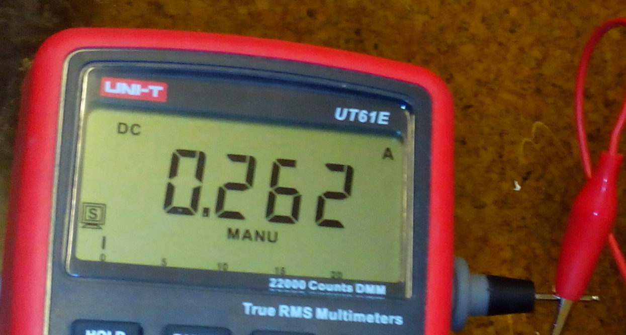
When booting, the current was jumping around 100mA, once the camera kicks in (h264 encoding) and wifi starts transmitting, it jumped to 260mA (couldn't use low range, so I just round up the last decimal).
during boot, jumps between 60-150mA

transmitting
Volts
Current times voltage equals power, in this case 3 watts. Considering that's with the sub-optimal regulator design (fairly low frequency and grossly oversized inductor), not too bad. I will be doing more measurements with a better regulator providing 3.3V directly.
Sadly, the Zero does not have the camera port or the connections to it on the board, which is a shame, so you have to use an A+ for the transmitter. Using the more powerful Pi versions for the transmitter is counterproductive, as the greater heard of horses also eats more (and generates more waste heat).

Obvious thing to do at 6 o'clock in the evening...

Yes, that's a zip-tie

I was kinda in a hurry to get it moving...

All it's missing is the kitchen sink...
Did just a few quick indoor tests, big surprise, a 1:10 RC car is too big for driving around a flat without wrecking it. Since it's dark, freezing and now snowing outside (and the 100cm TV is kinda hard to carry around), so I have to wait for better weather and a small display.

To come:
this (Zero has the same header, so it should work)
- some miniaturization (remove USB connectors and hardwire the wifi, use a more modern buck converter)
- weatherproofing
- lowering the power-hungriness
- dealing with the slight EMI issues (RC car and the wifi interfere with each other in various ways)
- different camera module (huge lens, maybe no IR filter for better low-light performance)

edit:

So I measured the 5V side, and the consumption is when transmitting is 2,15W, which is pretty much dead on 70% of the regulator input, so, quite a shitty buck regulator. A properly designed one should be capable of at least 85%, over 90% if done really well.
However keep in mind that these measurements do not include the absolute deviation, I'm too lazy to look it up and count it, if you're bored, I used a UT61 multimeter, current was on the 10A range.
Also there's the problem of switchmode PSUs, which notoriously confuse the fuck out of multimeters by the high frequency ripple, the UT61 is a true-RMS meter, but a cheap one, so...

Monday, September 7, 2015

Hobbyking ECO 6-10 200W & USB data

© Hobbyking

A while back, I bought this charger. May seem a little pricy, but I wanted the more powerful discharging. More on how that bites you in the ass later (fan's loud as fuck). Anyways, there was a USB port on the side, was even labeled as USB.
While as it seems that some of the Hobbyking ECO series use this connector for UART, this one is a real USB device, a CP2102 UART to USB bridge to be precise. If the PC finds a USB device once you plug it in, you have USB version. (huh, who would've thought...)
So, we have a UART bridge connected to a charger, now what.
For starters, you need the CP210x_VCP driver. (google, there's plenty links) Once that installs, you can actually connect to it with a serial monitor, that i can personally attest. However, after 30 minutes of trying different combinations of baud rates, parity, data, stop bits and hardware flow settings and still getting garbled nonsense, I gave up. There's like, only, 2240 permutations, and that's excluding the software flow control settings...oh, and 9600 baud, 8 bits, no parity and 1 stop bit does not work btw...
Turns out, there's actually custom software that can do all the work, the downside is that it's proprietary. The charger manual actually even mentions it - EAC200.
When googled, a company named Bantam keeps popping up. They even make a charger named "eStationBC610". 6-10...where have I heard that before...when in China, expect copies of everything.
Buuuut, since I'm cheap and don't feel like paying $20 for a CD and postage, I kept on searching.
As it turns out, good people still seem to exist, there's an opensource program that can do the same - DataExplorer.
DataExplorer is Java-based, there are 32bit and 64bit versions, watch out for that, the wrong one will install fine, but won't run. From what I understand, the 32 or 64 bit should be dependent on your version of Java, but from my experience of having 64bit Windows 7 Professional with both Java versions, I needed the 64bit.
Once you install everything, you have to choose the "eStationBC610", don't worry if nothing happens even if you have the charger connected, you have to start charging/discharging for it to communicate (which is weird, since the charger is sending something through the port even when idle.)

The moment you start charging, it comes to life
1 minute 20 seconds in
10 minutes 40 seconds in
Done

I'd call that a success, free (even open source) and it works...

Tuesday, April 28, 2015

Moar pictures of the Siemens EPD-1 guts


portion of the flat flex cable
Traces from top to bottom:
Ground (to case)
Negative power (ground)
Positive power
unknown*


The lower large pad is the negative battery terminal, the upper positive. This is where I connected a Li-ion cell and the unit did something.

The weird springy sheet metal clip...thing...holds this:

Absolutely no idea WTF

???

The center pin of this weird thing is the unknown* trace, the case is connected to ground.

Thursday, January 22, 2015

PC watercooling loop upgrade and update

Approximately 4 months have passed and I was looking for a new job again (dear ex-employer: fuck you) so I finally had time to finalize the project to what I consider version 1.0. Well, the real reason I did it was because of this:

The glue decided to take a break

The glue in top back edge of the reservoir decided to let go, forming an approx. 5cm crack, some 0.35mm wide. Small enough to not get noticed in the case and above the still waterline, so it probably was there a while since it had no reason to leak. Because of the way the system was kludged together, some time later I had to lean the case backwards a bit to keep the pump from sucking in small bubbles. (It makes noise when that happens) The result of this was that a puddle of water began to form on the top of the reservoir and started to drip down. Luckily nothing got destroyed, the PC did however crash, which was why I was examining the insides and found a puddle of water on the bottom. Not a very pleasant feeling I tell you...
Because the loop had to be drained, (top tip: if you need to drain your loop and don't want to make a mess, use a vacuum cleaner that can deal with water) I went ahead and decided to put the L fittings in.
I also took the block apart to see how it held up.

Not so well...
At least the seal worked

The block does indeed corrode, I suspect that is because the CPU heatspreader is grounded, thus there is potential between the brass fittings (which are connected to the hose braiding and that touches the case). Anyways, there is no measurable loss of material (the bottom is still almost 2.5mm thick like it was before) and judging by the amount of oxides, I will make a new block well before the old one becomes anywhere near being eaten through.
The only downside is lost cooling potential. I am running a FX-8320e and the temperature stays around 30°C at 18°C ambient temperature while idling, at full synthetic load it fairly quickly climbs to around 38°C and stays there. After terminating the load, it quickly falls back down, indicating that the block has a fair bit of heat resistance. Hopefully a new block will fix this, but overall I am very satisfied with the performance, the true test will come when summer hits and the ambient temps rise past 35°C...

After scrubbing the oxides off, I began reassembly.
These allow the L fittings to rotate without moving the threads in the plastic
In all its glory

This time, the block is sealed by air-curing neutral silicone.
Beware that not all silicones are ph neutral, most are acidic and corrode aluminium!

Block, it's hoses and pump are in

Radiator with fans (on the inside), reservoir and more hoses added

As if failing once is not enough...

I hate acrylic/CA glue as a building material. This will get replaced in the next version.

Complete with filling solution
Additions to this version include a fillport with ball valve and a T fitting at the pump. Forgot to take pictures with the graphics card inside. Some other day...

You will need these tools to complete the build

The crapload of wrenches is necessary because of the 3 different nut sizes, the universal one is needed because of limited space between some fittings where normal wrenches simply do not fit.
Next is an hex bit with holder (screws in the CPU block), the big hex key is to screw in and tighten the stationary part of the L fittings into the block (their inside is hex shaped) as there is no other way to do so.
Teflon tape is to seal the fittings in the plastic, everything else uses squishy silicone ring seals (blue box top left-ish).
Needle-nose pliers and screwdrivers to fix the heat exchanger in place, neutral silicone to seal the block itself.
Hose with screw-on L fitting, funnels, clamps and measuring cup to fill the loop. btw the coolant now contains about 10% non-toxic anti-freeze (some weird mix of various more complex alcohols, the pure form is quite sirupy) to keep algae and other crap out. Or at least dead.

Version 2.0 will feature a better block design that uses copper in reasonable amounts (thus being cheap) and most likely a graphics card cooling solution. I'm still toying with the idea of making the CPU cooling direct (water directly on the heatspreader), as it would drastically improve the thermal resistance problem and make the thing smaller.